
Interfacing LM35 Temperature Sensor with Arduino
Introduction
Temperature is one of the most commonly measured physical quantities in electronics projects, from simple home automation systems to industrial monitoring equipment.
Among the many sensors available for this purpose, the LM35 stands out as one of the most popular choices. With a typical accuracy of ±0.5°C, low power consumption, and a wide operating range (typically -55°C to 150°C depending on the package), it strikes an excellent balance between simplicity, cost, and performance.
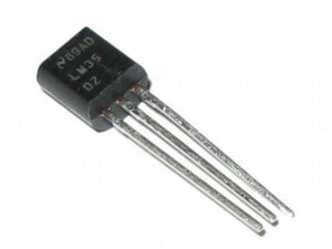
LM35 Temperature Sensor
In this tutorial, you’ll learn how to wire the LM35 to an Arduino, and through three practical examples, you’ll gain a solid understanding of this sensor so you can confidently include it in bigger projects.
How the LM35 sensor works
The LM35 works on the principle that the voltage across a transistor’s base-emitter junction changes in a predictable way with temperature — it decreases by a small, consistent amount (roughly 2mV) for every 1°C rise in temperature. This is a natural electrical property of semiconductor junctions.
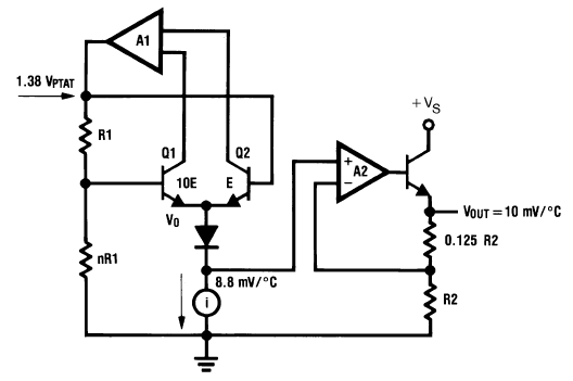
Inside the LM35 sensor
Inside the LM35, this voltage change is picked up and passed through a built-in amplifier circuit that scales and calibrates it precisely, so that the final output becomes exactly 10mV per °C. This internal calibration is what removes the need for the user to do any complex math or compensation — the sensor essentially does the conversion from “raw semiconductor behavior” to “clean, linear temperature signal” before the output ever leaves the chip.
You can find more information in the datasheet below.
When connected to an Arduino, the LM35’s analog output is read and converted into a temperature value through three distinct stages :
Stage 1: Analog Voltage → Digital ADC Value
The Arduino reads the LM35’s analog output using its built-in ADC and converts it into a digital value between 0 and 1023.
ADC_value = analogRead(A0)
Stage 2: Digital ADC Value → Voltage
This raw digital value is then converted back into an actual voltage, based on the Arduino’s reference voltage.
Voltage (mV) = (ADC_value / 1023) × 5000
Stage 3: Voltage → Temperature
Finally, the voltage is converted into a temperature reading using the LM35’s fixed 10mV/°C scale factor.
Temperature (°C) = Voltage (mV) / 10
ADC value
-
Voltage
-
Temperature
-
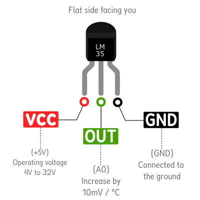
LM35 Sensor Pinout
The LM35 is most commonly found in a TO-92 package — the same small plastic, half-moon-shaped case used for many transistors. It has three pins:
Wiring the LM35 Sensor to the Arduino
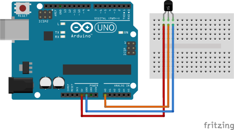
Warning : If you connect VCC and GND backwards, the LM35 will get hot instantly. If you feel heat coming from the sensor after connecting, disconnect immediately!
Example 1 : Reading temperature with LM35
This example shows how to read the LM35’s analog output and convert it into a temperature reading in degrees Celsius (°C) and degrees Fahrenheit (°F), displayed on the Serial Monitor. Keep the same wiring shown above.
const int sensorPin = A0;  // LM35 output connected to analog pin A0

void setup() {
  Serial.begin(9600);      // Start serial communication at 9600 baud
}

void loop() {
  int sensorValue = analogRead(sensorPin);           // Read raw ADC value (0-1023)
  float voltage = sensorValue * (5.0 / 1023.0);      // Convert ADC value to voltage
  float temperatureC = voltage * 100.0;              // Convert voltage to Celsius (10mV/°C)
  float temperatureF = (temperatureC * 9.0 / 5.0) + 32.0;  // Convert Celsius to Fahrenheit

  Serial.print("Temperature: ");
  Serial.print(temperatureC);
  Serial.print(" °C / ");
  Serial.print(temperatureF);
  Serial.println(" °F");

  delay(1000);  // Wait 1 second before next reading
}
Once uploaded, open the Serial Monitor (set to 9600 baud) to see the live readings :

The values update every second, reflecting real-time changes in the sensor’s surrounding temperature. Try holding the LM35 between your fingers or blowing warm air on it to see the readings rise.
Code explanation
Example 2 : Improving the Accuracy of readings with the Arduino's Internal ADC Reference
By default, an Arduino’s Analog-to-Digital Converter (ADC) compares incoming sensor voltage against the board’s main 5V power supply. Because the Arduino uses a 10-bit ADC, it chops that 5V range into 1024 equal digital steps .
At room temperature (25°C), the LM35 sensor only outputs 0.25V (equivalent to 51 digital steps out of 1024), and even at 100°C it barely reaches 1V (equivalent to 205 digital steps out of 1024). That means the ADC only covers a small slice of its full 5V range, and a lot of resolution just goes to waste.
5V reference
5% usedThis is where the internal 1.1V reference of the Arduino helps. Instead of spreading those 1024 steps across 5V, the Arduino spreads them across just 1.1V, so each step becomes much smaller -> about 1.07mV. Using the same example, that same 0.25V reading now corresponds to roughly 234 steps instead of 51. Same temperature, much more precision.
1.1V reference
91% usedWarning : When you activate the internal reference in code, the Arduino internally connects that 1.1V source to the AREF (Analog Reference) pin on the board. Do not connect any external wires or voltages to the AREF pin. Doing so will cause a short circuit inside the microcontroller and can permanently destroy your Arduino.
const int sensorPin = A0;  // LM35 output connected to analog pin A0

void setup() {
  Serial.begin(9600);      // Start serial communication at 9600 baud
  analogReference(INTERNAL);  // Use internal 1.1V reference (Uno/Nano/Mini)
  delay(1000);                // Allow reference voltage to stabilize
}

void loop() {
  int sensorValue = analogRead(sensorPin);           // Read raw ADC value (0-1023)
  float voltage = sensorValue * (1.1 / 1023.0);      // Convert ADC value to voltage
  float temperatureC = voltage * 100.0;              // Convert voltage to Celsius (10mV/°C)
  float temperatureF = (temperatureC * 9.0 / 5.0) + 32.0;  // Convert Celsius to Fahrenheit

  Serial.print("Temperature: ");
  Serial.print(temperatureC);
  Serial.print(" °C / ");
  Serial.print(temperatureF);
  Serial.println(" °F");

  delay(1000);  // Wait 1 second before next reading
}
Code explanation
Example 3 : Making thermometer with LM35 and 16x2 I2C LCD Display
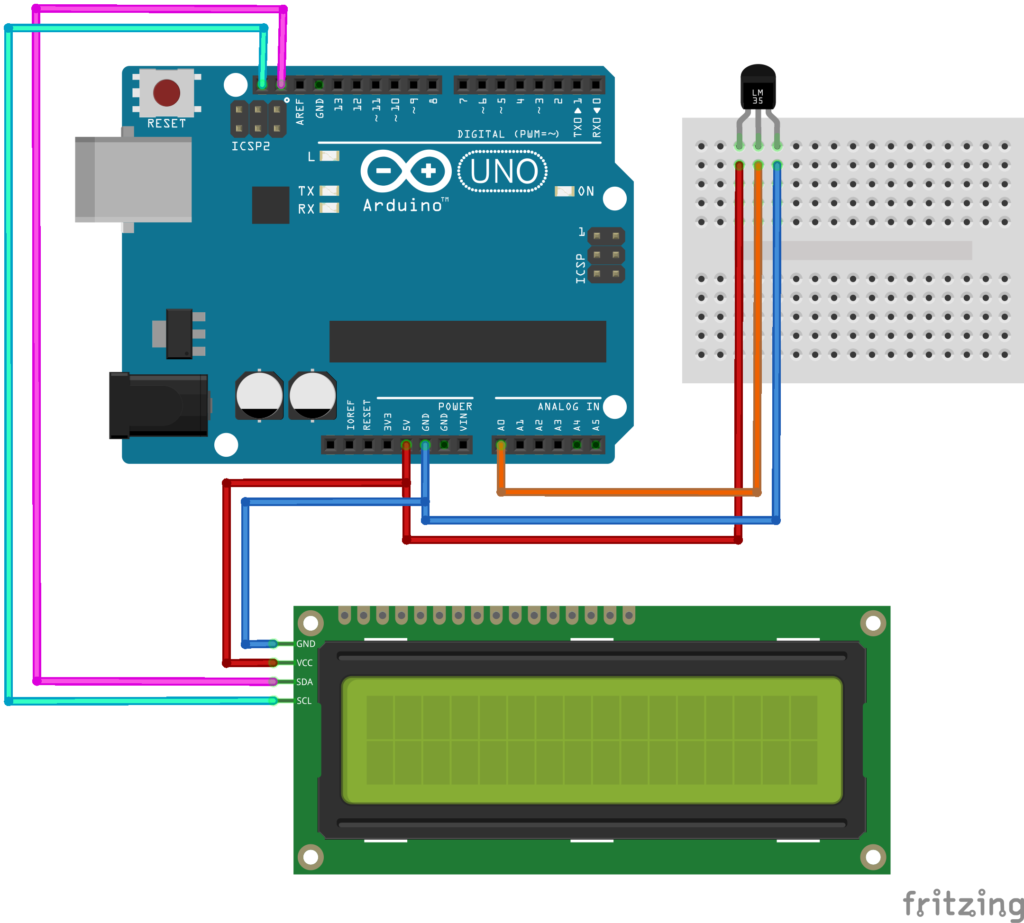
In this example, we read the temperature with the LM35 sensor, but instead of showing the readings on the Serial Monitor, we display them on a 16×2 I2C LCD. This means you can disconnect the PC after uploading the code and power the Arduino with a battery to create a standalone thermometer.
Update the connections as shown below.
#include <Wire.h>
#include <LiquidCrystal_I2C.h>

LiquidCrystal_I2C lcd(0x27, 16, 2);  // I2C address 0x27, 16 columns, 2 rows
const int sensorPin = A0;             // LM35 output connected to analog pin A0

void setup() {
  analogReference(INTERNAL);  // Use internal 1.1V reference (Uno/Nano/Mini)
  delay(1000);                 // Allow reference voltage to stabilize

  lcd.init();          // Initialize the LCD
  lcd.backlight();      // Turn on the backlight
  lcd.setCursor(0, 0);
  lcd.print("LM35 Thermometer");
  delay(1500);
  lcd.clear();
}

void loop() {
  int sensorValue = analogRead(sensorPin);           // Read raw ADC value (0-1023)
  float voltage = sensorValue * (1.1 / 1023.0);      // Convert ADC value to voltage using 1.1V reference
  float temperatureC = voltage * 100.0;              // Convert voltage to Celsius (10mV/°C)

  lcd.setCursor(0, 0);
  lcd.print("Temp: ");
  lcd.print(temperatureC);
  lcd.print((char)223);  // Degree symbol
  lcd.print("C");

  delay(1000);
}
The LCD will briefly show “LM35 Thermometer” on startup, then continuously display the room temperature. The reading updates every second and holds steady thanks to the internal reference